
Choosing the right deployment location
Much of BQN functionality requires seeing the subscribers’ individual IP addresses (for example, to limit each subscriber maximum rate). For that reason, it is important to deploy the BQN in a network position where there is no NAT between the BQN and the subscribers. There can still be NAT between the BQN and the subscribers, but in those cases, the rate and shaping limitations, and the subscriber metrics, will apply to the NAT IP address. TCP Optimization will also work if there is NAT, but it will not benefit from per-subscriber adaptations.
[.p-highlight-red]It is crucial to make sure that traffic through the BQN is symmetric: if the downlink traffic for any subscriber is going through the BQN, then all the downlink traffic and the corresponding uplink traffic for that subscriber must go through the BQN too [.p-highlight-red]
Otherwise, the BQN will not be able to limit the rate or do shaping for that subscriber (because it would not see all the traffic), and the TCP optimization could even block downloads towards that subscriber (because it would not see that some traffic has been acknowledged). Care must therefore be taken if there are redundant links for those links going through the BQN, so that only in case of failure are redundant links bypassing the BQN used. If there is load balancing among the links, all the load-balanced links must go through the BQN.
Regarding whether it is better to place the BQN closer or further from the subscribers, we must first consider only places where there is no asymmetric traffic and, preferably, no NAT towards the subscribers. Then, from a TCP Optimization perspective, it is better that the most difficult hops (e.g., a low-quality wireless backhaul link) are between the BQN and the subscribers, because the TCP Optimization will then help us over that difficult hop. In fact, a BQN could be installed on both ends of a very challenging transmission hop (like a satellite link), but we should also look at deployment options that result in a minimum number of BQN nodes.
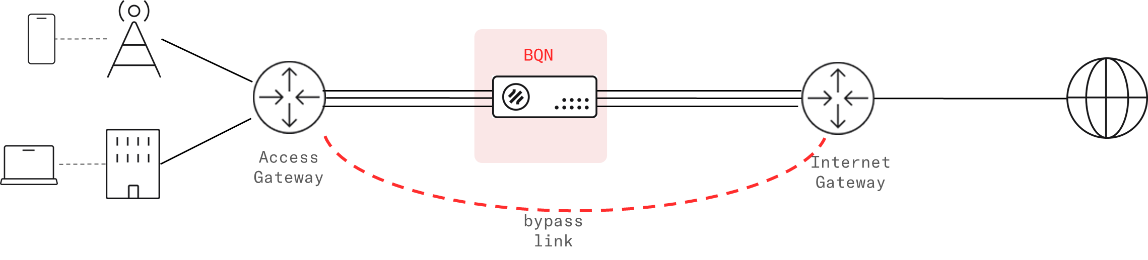
[.p-highlight-blue]It is recommended that a bypass path is established between the neighboring nodes of the BQN (Access and Internet gateways in the diagram above), so if there is a failure in the active link or the BQN, the traffic is automatically steered through the bypass. See the section 'Setting up a bypass' further down the page.[.p-highlight-blue]
Network Requirements
Management Interface Requirements
- One Management IP address, with mask and default gateway (e.g., 10.10.1.47/24 with default gateway 10.10.1.1).
- Remote access to the management IP address for TCP ports 22 (SSH) and 443 (HTTPS) from the Bequant support public IP address. This access can be set up with port forwarding rules in the router accessing the management network.
- Access from the BQN management IP address to the IP addresses and ports of the Bequant license manager (contact Bequant support for details about those IP addresses and ports).
- Access from the BQN management IP address to the NTP servers (UDP port 123) configured.
Datapath Requirements
Steering of traffic though the BQN must be bidirectional (all uplink and downlink traffic for the selected subscribers must go through the same BQN).
Traffic standards supported:
- [.c-highlight]IEEE 802.1Q[.c-highlight] (VLAN)
- [.c-highlight]IEEE 802.1ad[.c-highlight] (QinQ)
- [.c-highlight]IEEE 802.3ad[.c-highlight] (LACP)
- [.c-highlight]IETF RFC 2516[.c-highlight] (PPPoE): PPP compressed traffic is not supported.
- [.c-highlight]IETF RFC 3032[.c-highlight] (MPLS): VPLS and pseudowires are not supported
- [.c-highlight]IETF RFC 2784[.c-highlight] (GRE): supports unfragmented GRE packets with first two bytes set to zero (Checksum bit, reserved bits and version number) and protocol types IPv4, IPv6 or ethernet frames (of IPv4 or IPv6 content). Otherwise, the packets are relayed without further processing. Fragmentation inside the GRE tunnel is supported.
Traffic of supported type is automatically inspected by the BQN and does not require any special configuration. Non-supported traffic is transparently forwarded without any further processing.
[.p-highlight-blue]The maximum MTU supported is 2026. Packets exceeded this MTU maximum value will be discarded.[.p-highlight-blue]
Aggregate links through the BQN
Since the two ports of each wire are bridged transparently though the BQN, aggregate links can go through the BQN transparently over several wires. The <span class="character-highlight">LACP</span>, Cisco Etherchannel and Mikrotik/Linux bonding aggregate links will be established between the endpoints before and after the BQN, as if the BQN was not there.
[.p-highlight]The aggregated links going through the BQN, are no longer physical end-to-end links, so the link monitoring on both ends of the aggregate should not rely on electrical means (like "mii monitoring" in Mikrotik) and should be based on message exchanges, like LACP messages (preferably with fast-lacp), or ARP (in case of Mikrotik active-backup bonds).[.p-highlight]
Setting up a bypass
Bypass link
A bypass link can be set up at layer-2 (e.g., Mikrotik’s active-backup link bonding, or an active-backup LACP setup) or layer-3 (e.g., OSPF or BGP dynamic routing). Since the links are established directly between the two neighboring nodes, transparently with the BQN in the middle, the link monitoring mechanism should not be electrical (e.g., MII), but based on messages (e.g., ARP or fast LACP).
External bypass device
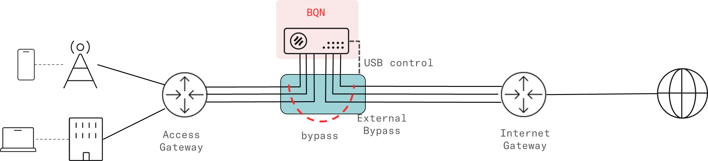
An external bypass device is connected to the external links and to the BQN. The device will trigger an internal bypass if it detects the BQN is down (monitoring takes place through a USB connection between the BQN server and the bypass device). It is enabled selecting Normal in Configuration->Interfaces->Bypass. It is also possible to force the bypass from the BQN with the option Forced Bypass in the same screen.
Currently, only Niagara devices are supported (e.g. Niagara bypass switch 3296).
Network card with internal bypass
A network card with an internal bypass can be used in BQN server. Currently, only Silicom devices based on Intel XL710-BM1, X540 and E810-C are supported (e.g. Silicon model PE210G2BPI9-SRD-SD or model P4CG2BPI51-ZL4). See Supported Network Interfaces for detailf of kernel requirements.
The card is controlled accessing via ssh to bqnsh.
To see the status of the card:
This example shows the default configuration, that will trigger the bypass if there is a power outage (POWER-CFG on and, when there is no bypass, it will steer the traffic through the BQN Software (STEER-CFG on). POWER-LIVE and STER-LIVE report the current status on the network card and should be equal to the configured state. The interface pair should match a wire.
To activate the bypass manually (for example to perform a planned maintenance task on the BQN server), the following configuration changes must be done on the master interface:
To steer the traffic back through the BQN software (e.g. once the maintenance task is complete), the changes are reverted:
It is also possible to disable the triggering of the bypass (for example, because an external bypass path based on dynamic routing is going to be used instead):
Connecting the BQN to the network
Management port
Connect the power supply and the management cable to the OAM port. If the server was installed from the iso, the management interface is the one selected during the installation process. Normally, the management interface is configured in the first integrated interface (the leftmost in the server motherboard, whose name is usually en0o1).

Switch the BQN server on and access the management GUI following the steps described in Login section.
The BQN factory management IP address is 192.168.0.121/24, with default gateway 192.168.0.1. The management user is bqnadm. If the server has been installed from scratch, the IP address and password will be those provided during the installation process.
If you need to change the management IP address or default gateway, see the section Changing the Management IP Address.
Verify date and time
Verify the date, time and time-zone in the Administration->SystemDate->Set Date & Time page are correct.
Verify connection to NTP servers and license manager
Access to the Bequant license manager is OK if the License Manager icon in the dashboard is green. Contact Bequant support for details about license manager IP addresses and ports.
Access to NTP servers can be checked in Administration->System Date-> NTP Servers, where some of the NTP entries should in connected state. The NTP servers may be changed (you can eliminate some of the default servers and/or add new ones). NTP server take some time to synchronize, so they may not be synchronized initially, but they should after a few hours.
Network interface mapping
To do the mapping of the physical network ports to the interface names shown in the BQN GUI, do the following:
- Connect one physical interface at a time (e.g. connect it to a free switch port or to a port in the BQN already mapped).
- Check in Status->Interfaces->Link State which interface changes the link state to up.
- Make sure you reload the page every time you change the physical connection, because the page does not reload automatically.
Connect subscriber traffic ports
Subscriber traffic interfaces are paired in wires, internally connected so the traffic received by one interface is sent to the other one and vice versa. Each wire in use needs both interfaces connected on the access and Internet sides. It is important to connect the interfaces correctly (otherwise, the system performance will be affected).
Use the network interface mapping to locate the ports of each wire defined in Configuration->Interfaces->Data Wires.

The network interfaces in use must be up and with the link detected. Both can be monitored in the GUI Status->Interfaces->Link State

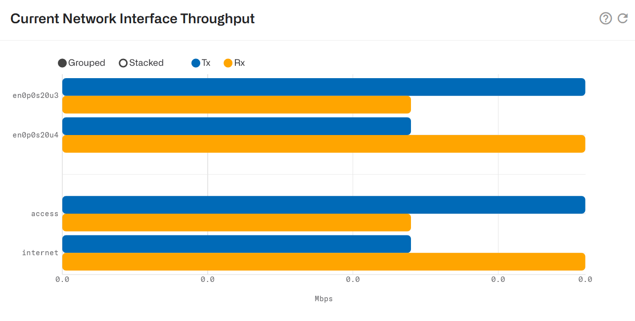
Once the traffic is steered, you can see its instant value in Status->Interfaces->Throughput.
And that is all. The installation is done.
Lorem ipsum dolor sit amet, consectetur adipiscing elit. Suspendisse varius enim in eros elementum tristique. Duis cursus, mi quis viverra ornare, eros dolor interdum nulla, ut commodo diam libero vitae erat. Aenean faucibus nibh et justo cursus id rutrum lorem imperdiet. Nunc ut sem vitae risus tristique posuere.
Lorem ipsum dolor sit amet, consectetur adipiscing elit. Suspendisse varius enim in eros elementum tristique. Duis cursus, mi quis viverra ornare, eros dolor interdum nulla, ut commodo diam libero vitae erat. Aenean faucibus nibh et justo cursus id rutrum lorem imperdiet. Nunc ut sem vitae risus tristique posuere.
Lorem ipsum dolor sit amet, consectetur adipiscing elit. Suspendisse varius enim in eros elementum tristique. Duis cursus, mi quis viverra ornare, eros dolor interdum nulla, ut commodo diam libero vitae erat. Aenean faucibus nibh et justo cursus id rutrum lorem imperdiet. Nunc ut sem vitae risus tristique posuere.